Monday, 30 March 2020

The Cliffhanger: Edward Randy repair log

Got for repair a "The Cliffhanger: Edward Randy" (known in Japan simply as Edward Randy) PCB , a side-scrolling action-adventure arcade game released in Japan by Data East in 1990.Board was in decent condition although with some sign of previous repairs :


Game booted up but displayed with the only RED color, BLUE and GREEN were missing at all :


 The logic probe confirmed that signals were both stuck HIGH:


I traced them back to emitter of two NPN (BC337 type) transtitors  :


I noticed that pinout of transistor was adapted to the PCB footprint, this probably because manufacturer didn't have the right part or did it for costs saving.A closer inspection revealed that the base and collector (tied to VCC) legs of the BLUE and GREEN transistors were shorted each other causing stuck signals.Clearing the shorts restored the correct colors, in this way I was able to better see what was going on.The game had issue with both sprites and backgrounds :


The sprites are generated by the custom ASIC marked '52' which was previously reworked and repaired in some pins:


I reflowed it but this didn't lead to great improvements, the sprites were still scrambled.Relevant data are stored in ten 4Mbit MASK ROMs (pin to pin compatible with 27C400 EPROM) :


Pressing down the PCB in the highlighed area of above picture restored the sprites hence there could be a bad contact somewhere.I probed each MASK ROM with my oscilloscope and found a floating address line on pin 1 (A17, the higher address line) of the one @9Y :


I run a jumper wire from this pin to pin 1 of the near device (address bus is shared among all sprites MASK ROMs) and I got all sprites properly rendered but, obviously, backgrounds were still glitched  :


 Tilemap data are stored in three 4Mbit MASK ROMs :


Checking these devices I found again a broken connection between two address lines, I promptly patched it with some wire :


This made the trick and all the graphics were fully restored.I was about to close this repair when, playing some games, I noticed that some audio samples were missing:


Here's how it should sound compared to a MAME recording:
 

All audio samples are generated by a couple of OKI MSM6295 ADPCM IC :


Checking their analog outputs with an audio probe revealed that the missing samples were properly generated but then lost somewhere before reaching the main amplifier.Always with my audio probe I started to "listen" to various points of analog audio circuit narrowing the area where fault lied.While doing it I came across to this :


The positive lead of a 10uf 16V electrolytic capacitor was detached from body interrupting the audio signal.Replacing the capacitor gave the missing audio samples back and fixed board completely.Repair accomplished.


Sunday, 22 March 2020

Mr. Do's Wild Ride repair log

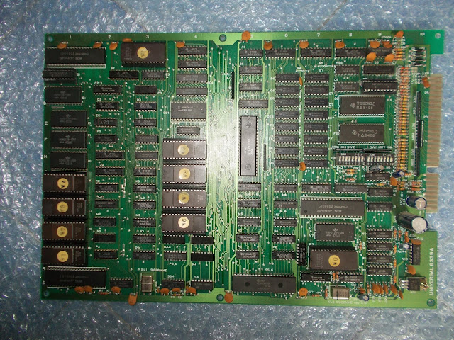
Received for repair an original Mr. Do's Wild Ride PCB, a game released in 1984 as the third chapter in Universal's Mr. Do! arcade series  :


Board booted up, game was playable with sound too (I hooked up an external audio amplifier since the board lacks of it) but graphics were glitched by vertical lines :


 Looking at PCB I spotted two rows of 4164 devices which are part of the line buffer circuit:


 They are 64 x 1-bit dynamic RAMs, here's pinout :


The oscilloscope revealed floating outputs on three of them,  you can see in below picture the bad signal (stuck at undefined voltage logic level of 1.52V) compared with an healthy one :


I removed the chips :


The out-of-circuit testing confirmed they were bad :


I installed sockets and good ICs :


No more glitches on the screen :


Board 100% working and another successful repair.


Friday, 20 March 2020

Taito 'PC060HA' reproduction

Another custom IC successfully reproduced! Thanks to the awesome job of 'furrtek' (with my little contribution) no more panic will assault us whenever we encounter a faulty Taito 'PC060HA' custom IC on our beloved arcade PCBs.
The chip in question is a 28PIN DIP 600 mil :


Technically speaking it acts as communication interface between the main and sub CPUs.It can be found on many Taito boards, this should be a complete list :
  • Asuka & Asuka
  • Cameltry
  • Champion Wrestler
  • Daisenpu
  • Darius
  • Exzisus
  • Fighting hawk
  • Gokidetor
  • Hit The Ice
  • Master of Weapons
  • Midnight Landing
  • Operation Wolf
  • Rainbow Islands
  • Rastan
  • Taito Bingo Wave
  • Tetris
  • Top Speed
  • Violence Fight
  • Volfied

As said,  'furrtek' made a fanstatic job and took care of almost everything, decapping the IC (kindly donated by 'Ace`' from UKVAC forums, thanks again to him) and tracing the schematics from the silicon die translating them into Verilog code.I simply made the final and easy part designing a proper board based on an Altera (or Atmel) CPLD in TQFP100 package :


After some work needed to optmize the Verilog code on boards with different clock of Z80 CPU (I sent 'furrtek' a Cadash and Master of Weapon PCBs for this purpose) I successfully tested the replacement on all my arcade boards that carry this custom IC, it works flawlessly:


 Thanks again to 'furrtek' and all other people involved in this great achievement.
  

Wednesday, 11 March 2020

Namco '04XX' reproduction

After the recent reproduction of the Namco '02XX' custom IC I took into account the one marked '04XX ' (where 'XX' digits identifies date/lot production).It has same DIP28 600 mil package but different functions being a motion object controller/scratch RAM to CPU bus interface :


It can be found on these PCBs :
  • Dig Dug
  • Galaga
  • Pacland
  • Mappy
  • Pole Position
  • Super Pac-Man
Replacements of this Namco '04XX' are available in CPLD or FPGA but, as always, I made my own reproduction using a different approach.Bootleg boards came handy for my purpose as they usually re-engineer the functions of custom ICs with common parts.I traced the equivalent circuit by comparing a bootleg to an original board and made a first "quick and dirty" prototype with thru-hole parts just to validate the design:


 It worked flawlessly on all different boards I tried (Dragon Buster, Galaga, Pac-Land and Toypop)


Now that the replacement circuit has been verified I can think about an SMD or even CPLD version of my Namco '04XX' custom IC reproduction.Stay tuned.

Tuesday, 10 March 2020

Namco '02XX' reproduction

Here's my own implementation of the Namco '02XX' custom chip.The part in question comes in a DIP28 600 mil package with stamped number of four digits (but the 3rd and 4th digits can vary because they actually refers to the lot/date production hence the first two digits really matters) Technically speaking it's a custom shift register for data from graphics ROMs.It can be found on not so many boards like Galaga, Dig Dug and Pole Position.


As you may know, someone else already reproduced this custom ICs using complex programmable logic devices or FPGA but I decided to do my version anyway.As I always I do, I started my work from some bootleg boards observing how the functions of the custom have been reversed with simple logics.I was able to extrapolate the equivalent circuit and then route it to a board layout of same dimensions of original part thanks to the use of surface mounted devices :


The design was right because I could successfully test my reproduction on a Galaga PCB :


Monday, 9 March 2020

Black Tiger repair log

Some months ago I purchased from USA an untested original Black Tiger PCB, I was looking for it since ages because I had only bootlegs so far.For the uninitiated, Black Tiger (known in Japan as Black Dragon) is a 1987 platform game released  by Capcom.
PCB is a two stack one with a CPU and VIDEO board :


On first power up it turned out game was fully playable with sound but background graphics were wrong affecting also the priority with sprites  :


All the circuit that generates the backgrounds lies on bottom VIDEO board.There are four 27512 OTP ROMs storing the relevant data.Then, shortcircuiting some data/address lines, I could figure out that a 8K x 8-bit SRAM was involved too:


The background graphics rendered in wrong position led me think about an addressing problem of the above mentioned RAM.I figured out part of the addressing circuit and all was normal while checking it until I came across two 74LS273 @10F and 11H


Most of outputs of the two ICs were inactive while inputs toggling and clock present, here's a snap from a logic analyzing :


Once removed the two ICs failed the out-of-circuit test :


I installed round machined sockets and good ICs :


 This fixed the issue :


 I tested the game and no other problem was found.Repair accomplished.


Wednesday, 4 March 2020

Cobra-Command repair log

Received for repair this pretty rare original Cobra-Command PCB, a 2D side-scrolling helicopter shooter released by Data East in 1988  :

On power up I got nothing on screen, no sign of life, board was dead.I checked the RGB and SYNC pins on the JAMMA edge connector and they were silent meaning the video timing circuit was not running at all :


Tracing the signals upstream lead me to one of the two surface mounted custom ICs marked 'L7B0072 BAC 06'  (the one @11E) 


I found its pinout on Robocop and Heavy Barrel schematics :


Probing its outputs I found that most of them were floating, stuck at undefined logic voltage level of +1.44V :


This was not new to me, this custom IC is well known to be prone of faiure, you can find several repair logs on the net mentioning it, like this Robocop one on JAMMArcade :


Having no spare I asked the owner of the PCB to look for a donor board and after some time he sent me a dead Midnight Resistance PCB which carries two of this 'BAC 06' custom ICs :


 I removed the suspicious bad one and soldered in the spare:


The board sprang to life but playing some games I noticed that some backgrounds were messed up and the board randomly freezed :


In this comparison with a MAME snapshot you can clearly notice the corruption of background graphics :


Part of tilemap graphics data are stored in four 27256 OTP ROM :


Probing them revealed some address lines were stuck LOW :


These are generated by the other 'BAC 06' custom IC but they first go through a couple of 74LS273 before reaching the ROMs :


Doing some logic analyzing of the 74LS273 @15B revealed most of outputs were amost inactive while inputs were toggling and clock present too :


 The IC was likey faulty hence I removed failing the out-of-circuit testing :


Fitted a good IC :


Background graphics were restored :


Board fully working again and another repair accomplished.