Wednesday 25 December 2019

Vendetta repair log

Yet another PCB bought in a lot, a Konami Vendetta :


The board was in good shape but played almost 'blind' as most of graphics was missing :


I experienced this kind of issue different times on other Konami boards like in these past repair from me (thanks to Porchy for allowing hot links from JAMMArcade) 

 https://www.jammarcade.net/the-simpsons-repair-log-3/

 https://www.jammarcade.net/g-i-joe-double-repair-log-3/

 The cause was due to a bad '053251' custom ASIC :


As MAME source says, this custom takes on input different layers of graphics as well as some priority bits and outputs 11 bit of palette index plus two shadow bits :


Probing the outputs revealed they were dead, stuck at LOW or HIGH logical level :


Having a spare I decided to replace it :


I soldered down the spare repairing a lifted trace at same time (some green lacquer used to hold the wire in place) :


In ths way most of graphics were restored but the sprites were wrong with parts of them spread on the screen  :


I launched a MASK ROM check which reported three bad 8Mbit devices  :


This was possible but unlikely although we all know Konami MASK ROMs are prone to failure.
On this board and similar hardware the sprites generation is entirey handled by a couple of surface mounted custom ASICs.Specifically the '053246' generate the addresses for the MASK ROMs and the '053247' processes their data :


Judging from the issue (parts of sprites misplaced on screen) I was more inclined to think about an addressing problem hence I decided to replace the '053246'.It came off quite easily with my hot air station :


 Soldered down the spare :


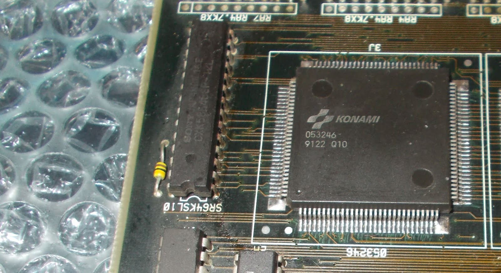
Powered the board up again and sprites were now correctly displayed :


No further issues found, board 100% working.Job done.


Friday 20 December 2019

Demons's World repair log #1

Another PCB found in a recent job lot purchase :


Board was dead, no sign of life.Dumping some EPROMs allowed me to identify it as Demon's World, a run and gun arcade video game developed by Toaplan.
Probing the 68000 main CPU revealed both /HALT and /RESET pins were stuck low :


The reset circuitry is a typical one built around the 'PST518' voltage detector IC plus all parts needed by its typical application circuit (resistors and a capacitor)


In particular the role of the capacitor is primary because, when the power supply voltage drops below a certain threshold, it suddenly discharges generating thus the required reset signal.
I removed this 10uF 16V electrolytic capacitor and measured it out-of-circuit:

As you can see from above picture, its capacitance was OK but the ESR was beyond typical values according to this table :


 Fitted a good capacitor and the board booted up into game but the colors were clearly wrong :


Inspecting the board I noticed some burnt resistors just near the JAMMA edge connector :


These resistors are part of the R/2R ladders (one for each RGB color) used to convert palette digital bits into analog signal.I figured out each R/2R is a 5-bit DAC with values of 220-470-1000-2200-4700 Ohm.Measuring them in-circuit gave me good values except for one that showed high resistance whereas it had to be 220 Ohm :


I replaced it but no changes, colors were still wrong.Measuring in-circuit the replaced resistor gave me a value of only 133 Ohm hence there had to be something holding it low.One side of this resistor is tied to the output (pin 12) of a 74LS273 @24M which was almost shorted to GROUND :


I removed the IC :


It failed the out-of-circuit testing exactly in the gate of shorted output :


Installed a good IC :


This restored correct colors :


 Board 100% fixed and a good (weird...) game added to my collection.


Tuesday 17 December 2019

Snow Bros repair log

Got this original Snow Bros PCB in a recent PCB lot purchase  :


At first power up the board booted up into game but I immediately noticed an issue concerning the graphics, all the backgrounds were fashing :


This is a common problem on this kind of board, there are four 64 x 4-bit dynamic RAMs that very often go bad causing screen artifacts:


Probing them with a scope I found the one @IC26 with almost inactive data outputs (good signal on the left of below picture) :


Sure enough I removed the IC :


It failed the out-of-circuit testing :


A new DRAM chip fixed the issue and I was archiving the board as fully repaired but playing some games I noticed the sound was faint even if I set the volume at highest level by acting on potentiometer:


This is a common issue too because this board does use in sound section a little custom IC (in SIL package) marked 'PX4460' :


This custom IC has inside some passive parts (resistors and capacitors) needed by the typical application circuit of the LA4460 amplifer and most of times internal capacitors fail causing a low or absent sound.I could try to repair the custom or install needed parts directly on PCB (board is already prepared for this) but I opted to replace the part with a reproduction of mine :


In this way the sound was restored loud and clear.Repair accomplished.


 P.S.

Here is the origanal post about the 'PX4460' reproduction I made time ago :

https://www.jammarcade.net/gals-panic-repair-log-and-kaneko-px4460-lpf6k-reproduction/


Saturday 7 December 2019

Sega '315-5012' reproduction

Here is a new reproduction of a custom IC I recenty made.This time I took into account the one marked '315-5112' found on Sega System 1/2/16A PCBs as well as unique hardware like Space Harrier and Hang On.Techically speaking it's a 48 pin DIP part (600mil wide) which accomplishes graphical functions generating the sprites and it's always used in pair with the smaller '315-5011' (which is the sprite line comparator) 


As always I studied how functions of this custom IC were reverse-engineered on bootleg boards.I was able to extrapolate the equivalent circuit and routed it to a proper board layout using thru-hole parts for this first testing made just to validate schematics:


 The replacement board worked fine :


Happy with result I decided to do a version based on an Altera +5V CPLD :


The hardware is made but software part not yet due to my limited knowledge with complex programmable logic and hardware description language so any help is welcome!

Sunday 17 November 2019

Raiden repair log

Received some time ago from Portugal this faulty Raiden PCB for repair (actually the hardware revision with Altera EPLDs) 


A said, the board was not properly working since on power up it was stuck on a static screen on which you could insert coin but nothing more :


Main (and SUB) CPU is a NEC V30 (real part name uPD70116) 

Probing it revealed that HALT pin (active HIGH) was asserted hence the CPU stopped its processing putting its busses into a high-impedance (or tri-state if you want) state :

The main CPU uses four 8k x 8-bit static RAMs:

 
Probing them with a scope revealed weak signals on data lines of the ones @U028 and U021, here's a comparison with an healtly signal on the left of the below picture :


This and the fact that RAM chips were Toshiba TMM2063 (so very prone to failure) lead me to remove them :


Both chips faied the out-of-circuit testing :


Installed sockets and fresh RAMs :


I powered board up and it booted into game with no further issues.Repair accomplished.


Sunday 3 November 2019

Golden Axe: The Revenge of Death Adder repair log

Received some time ago from USA a Golden Axe: The Revenge of Death Adder PCB for repair (a beat'em up released in 1992 by Sega on System 32 hardware)


Game played absolutely fine but sound was totally absent.Putting fingers on solder side of amplifier resulted in a buzzing noise hence analog sound circuit was doing its job and nature of fault was digital :


I went into TEST MODE and run a ROM/RAM check which reported a bad device @IC16 :


The device is a 8k x 8-bit static RAM which is part of the digital audio circuit ruled by a Z80 CPU, this perfectly explained the lack of sound :


Obviously the first thing I did was to remove the chip and test it out-of-circuit but it turned out to be good so I socketed and reinstalled it.Probing the the three control lines (/CE, /OE, /WE) with a scope revelaled static signals :


I traced them back to a custom ASIC @IC38 marked '315-5385' (in QFP128 package), a quick search on the net told me it's was the system controller/timer :


Having a faulty motherboard I decided to try the swap.The chip came off quite easily with hot air :

 The spare was installed and all pins checked under a microscope for possible bridges :


I powered the board up again and sound was fully restored.Another repair accomplished.


Tuesday 29 October 2019

Image Fight repair log

Received from Japan an Image Fight PCB for repair (game is a vertical shooter  developed and published by Irem on M72 hardware)


On power up the board seemed to properly boot, something moved on screen but then got stuck on garbage :


As many of  you may know, this is a three stack set hence, having a good R-Type boardset, I started to swap boards.I was able to narrow the fault in the bottom PCB :

First of all I probed these four 8k x 8-bit static RAMs @IC34-IC35-IC36-IC37 :


I found that their WRITE ENABLE input (pin 27) was stuck high, no activity/pulsing like observed on my good R-Type :


Tracing the signals back I could not find anything abnormal until I came across a 74LS32 @IC51 :


 The logic analyzer showed no LOW pulsing on output pin 11 when inputs 12 and 13 got asserted :


I piggybacked the device and board booted into game although background graphics were corrupted :


I removed the TTL device and it failed the out-of-circuit testing :


Time to install some machined round socket and a good IC :


The next power up gave me a fully working game with no other issue.Repair accomplished.