Wednesday, 25 December 2019

Vendetta repair log

Yet another PCB bought in a lot, a Konami Vendetta :


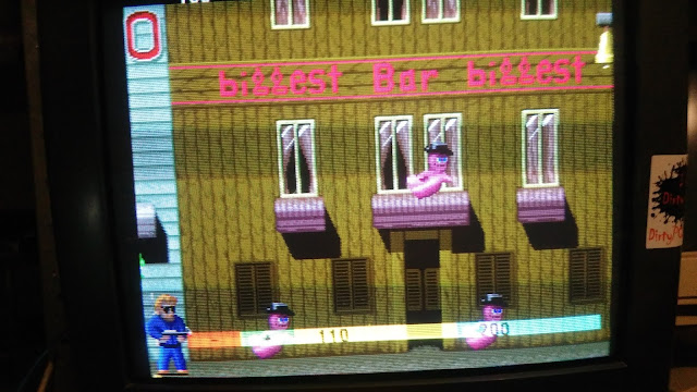
The board was in good shape but played almost 'blind' as most of graphics was missing :


I experienced this kind of issue different times on other Konami boards like in these past repair from me (thanks to Porchy for allowing hot links from JAMMArcade) 

 https://www.jammarcade.net/the-simpsons-repair-log-3/

 https://www.jammarcade.net/g-i-joe-double-repair-log-3/

 The cause was due to a bad '053251' custom ASIC :


As MAME source says, this custom takes on input different layers of graphics as well as some priority bits and outputs 11 bit of palette index plus two shadow bits :


Probing the outputs revealed they were dead, stuck at LOW or HIGH logical level :


Having a spare I decided to replace it :


I soldered down the spare repairing a lifted trace at same time (some green lacquer used to hold the wire in place) :


In ths way most of graphics were restored but the sprites were wrong with parts of them spread on the screen  :


I launched a MASK ROM check which reported three bad 8Mbit devices  :


This was possible but unlikely although we all know Konami MASK ROMs are prone to failure.
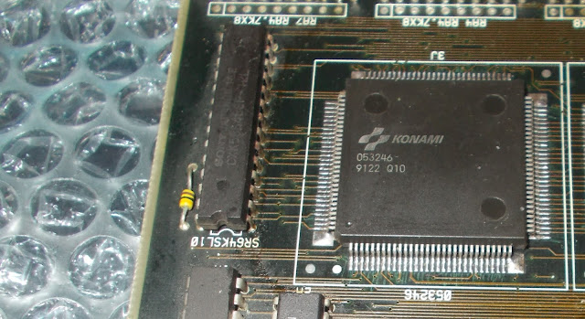
On this board and similar hardware the sprites generation is entirey handled by a couple of surface mounted custom ASICs.Specifically the '053246' generate the addresses for the MASK ROMs and the '053247' processes their data :


Judging from the issue (parts of sprites misplaced on screen) I was more inclined to think about an addressing problem hence I decided to replace the '053246'.It came off quite easily with my hot air station :


 Soldered down the spare :


Powered the board up again and sprites were now correctly displayed :


No further issues found, board 100% working.Job done.


Friday, 20 December 2019

Demons's World repair log #1

Another PCB found in a recent job lot purchase :


Board was dead, no sign of life.Dumping some EPROMs allowed me to identify it as Demon's World, a run and gun arcade video game developed by Toaplan.
Probing the 68000 main CPU revealed both /HALT and /RESET pins were stuck low :


The reset circuitry is a typical one built around the 'PST518' voltage detector IC plus all parts needed by its typical application circuit (resistors and a capacitor)


In particular the role of the capacitor is primary because, when the power supply voltage drops below a certain threshold, it suddenly discharges generating thus the required reset signal.
I removed this 10uF 16V electrolytic capacitor and measured it out-of-circuit:

As you can see from above picture, its capacitance was OK but the ESR was beyond typical values according to this table :


 Fitted a good capacitor and the board booted up into game but the colors were clearly wrong :


Inspecting the board I noticed some burnt resistors just near the JAMMA edge connector :


These resistors are part of the R/2R ladders (one for each RGB color) used to convert palette digital bits into analog signal.I figured out each R/2R is a 5-bit DAC with values of 220-470-1000-2200-4700 Ohm.Measuring them in-circuit gave me good values except for one that showed high resistance whereas it had to be 220 Ohm :


I replaced it but no changes, colors were still wrong.Measuring in-circuit the replaced resistor gave me a value of only 133 Ohm hence there had to be something holding it low.One side of this resistor is tied to the output (pin 12) of a 74LS273 @24M which was almost shorted to GROUND :


I removed the IC :


It failed the out-of-circuit testing exactly in the gate of shorted output :


Installed a good IC :


This restored correct colors :


 Board 100% fixed and a good (weird...) game added to my collection.


Tuesday, 17 December 2019

Snow Bros repair log

Got this original Snow Bros PCB in a recent PCB lot purchase  :


At first power up the board booted up into game but I immediately noticed an issue concerning the graphics, all the backgrounds were fashing :


This is a common problem on this kind of board, there are four 64 x 4-bit dynamic RAMs that very often go bad causing screen artifacts:


Probing them with a scope I found the one @IC26 with almost inactive data outputs (good signal on the left of below picture) :


Sure enough I removed the IC :


It failed the out-of-circuit testing :


A new DRAM chip fixed the issue and I was archiving the board as fully repaired but playing some games I noticed the sound was faint even if I set the volume at highest level by acting on potentiometer:


This is a common issue too because this board does use in sound section a little custom IC (in SIL package) marked 'PX4460' :


This custom IC has inside some passive parts (resistors and capacitors) needed by the typical application circuit of the LA4460 amplifer and most of times internal capacitors fail causing a low or absent sound.I could try to repair the custom or install needed parts directly on PCB (board is already prepared for this) but I opted to replace the part with a reproduction of mine :


In this way the sound was restored loud and clear.Repair accomplished.


 P.S.

Here is the origanal post about the 'PX4460' reproduction I made time ago :

https://www.jammarcade.net/gals-panic-repair-log-and-kaneko-px4460-lpf6k-reproduction/


Saturday, 7 December 2019

Sega '315-5012' reproduction

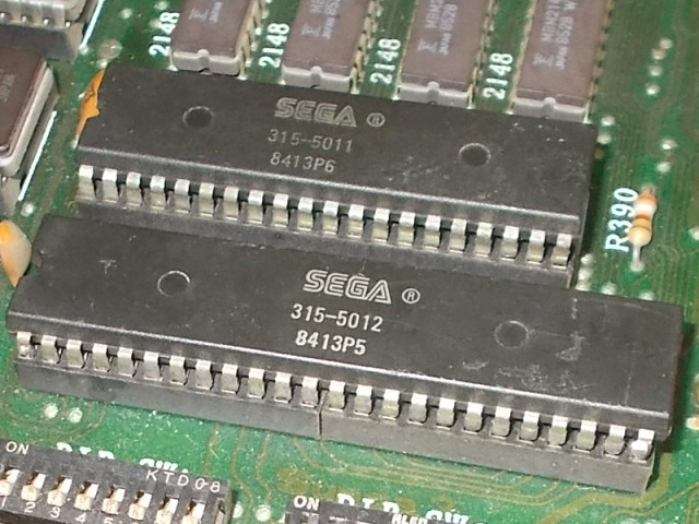
Here is a new reproduction of a custom IC I recenty made.This time I took into account the one marked '315-5112' found on Sega System 1/2/16A PCBs as well as unique hardware like Space Harrier and Hang On.Techically speaking it's a 48 pin DIP part (600mil wide) which accomplishes graphical functions generating the sprites and it's always used in pair with the smaller '315-5011' (which is the sprite line comparator) 


As always I studied how functions of this custom IC were reverse-engineered on bootleg boards.I was able to extrapolate the equivalent circuit and routed it to a proper board layout using thru-hole parts for this first testing made just to validate schematics:


 The replacement board worked fine :


Happy with result I decided to do a version based on an Altera +5V CPLD :


The hardware is made but software part not yet due to my limited knowledge with complex programmable logic and hardware description language so any help is welcome!